Showing posts with label nozzles. Show all posts
Showing posts with label nozzles. Show all posts
Saturday, August 8, 2015
How to use the Nilfisk Alto 'Click and Clean' pressure washer accessories system
Background
Nilfisk Alto pressure washers have a common pressure washer water outlet that measures about 22mm in diameter. The actual thread is 1/2" BSP. The Nilfisk Alto hose and trigger gun screw onto the machine and the gun has half of the lance moulded into the trigger. The power washers (Domestic use machines only) all have a bayonet outlet on the trigger gun.The Nilfisk Alto bayonet system has remained widely unchanged since the 1980's although construction materials have changed from brass metal to cheaper plastics.
So What is Click and Clean ?
When Nilfisk Alto changed over from metal to plastic manufacturing they developed a way of quickly attaching the nozzle to the lance. This was introduced around year 2000 and is still in use today (2014). The Premium power washer models like the P series (P150.1 etc) still use the older bayonet system and have spray nozzles with a brass bayonet.
This is an Adaptor image that has the Click and Clean connector on the Left and the Bayonet lug recesses can be seen on the middle towards the right. You can see a selection of Click & Clean power washer accessories for sale in the UK by sparesgiant.com
How to remove a click and clean nozzle from the pressure washer spray lance
At the end of the spray lance close to where the water exits, you should see a blue button. Press the button and the nozzle will be ejected.
Riello Burner information and Instruction.
Riello Burner information and Instruction.
In this Blog I will share some advice on general maintenance and how to keep your Riello burnerhappily running for as long as possible, as well as showing a faults, possible causes and solutions table. This will help should you choose the correct spare part should you need one.
Maintenance frequency. The combustion system should be checked at least once a year by a representative of the manufacturer or another specialised technician. They can advise on spares required is necessary.
Combustion. The optimum calibration of you Riello burner requires an analysis of the flue gases. Significant differences with respect to the previous measurements indicate the points where more care should be exercised during maintenance.
Pump. The delivery pressure must be stable. Unusual noise must not be evident during pump operation. If the pressure is found to be unstable or if the pump runs noisily, the flexible hose must be detached from the line filter and the fuel must be sucked from a tank located near the Riello burner. This measure permits the cause of the anomaly to be traced to either the suction piping or the pump. If the pump is found to be responsible, check to make sure that the filter is not dirty. The vacuum meter is installed upstream from the filter and consequently will not indicate whether the filter is clogged or not. Contrarily, if the problem lies in the suction line, check to make sure that the filter is clean and that air is not entering the piping.
Flexible hoses. Checks to make sure that the flexible hoses are still in good condition and that they are not crushed or otherwise deformed. Check periodically the flexible pipes conditions.
Fuel tank. Approximately every 5 years, or whenever necessary, suck any
Water or other impurities present on the bottom of the tank using a separate pump.
Filters.Check the following filter boxes: on fuel supply line; in the pump, and clean or replace as required. If rust or other impurities are observed inside the pump, use a separate pump to lift any water and other impurities that may have deposited on the bottom of the tank. Then clean the insides of the
Pump and the cover sealing surface.
Nozzles. Do not clean the nozzle openings; do not even open them. Replace the nozzles every year or whenever necessary. Combustion must be checked after the nozzles have been changed
Combustion head. Check to make sure that all the parts of the combustion head are in good condition, positioned correctly, free of all impurities, and that no deformation has been caused by operation at high temperatures
Fan. Check to make sure that no dust has accumulated inside the fan or on its blades, as this condition will cause a reduction in the air flow rate and provoke polluting combustion.
Boiler. Clean the boiler as indicated in its accompanying instructions in order to maintain all the original combustion characteristics intact, especially the flue gas temperature and combustion chamber pressure. Leave the Riello burner working without interruptions for 10 min. and set rightly all the components stated in this manual.
Faults / Solutions Here below you can find some causes and the possible solutions for some problems that could cause a failure to start or a bad working of the burner. A fault usually makes the lock-out lamp light which is situated inside the reset button of the control box. When lock out lamp lights the burner will attempt to light only after pushing the reset button. After this if the burner functions correctly, the lock-out can be attributed to a temporary fault. If however the lock out continues the cause must be determined and the solution found.
FAULTS | POSSIBLE CAUSES | SOLUTION | |
The riello burner will not start when the | Lack of electrical supply | Check the presence of voltage in the L-N clamps | |
limit stat is closed. | of the control box. | ||
Check the fuses | |||
Check the safety thermostat limited is not locked out | |||
The photoresistance see false light. | Eliminate any false light | ||
Resistance of heating resistance | Replace | ||
The connections in the control box are | Check and connect all the plugs. | ||
incorrectly inserted. | |||
Riello Burner runs normally in prepurge | The Photoresistance is dirty | Clean it | |
and ignition cycle and then locks out | The Photoresistance is defective | Replace with spare | |
after 5 seconds | Flame moves away of fails | Check the pressure and output fuel | |
Check air output | |||
Replace nozzle with a spare | |||
Check coil of solinoid valve | |||
Riello burner starts with an | The ignotion eletrodes are incorrectly | Adjust them according to instrictions | |
ignition delay | positioned | ||
Air output is too high | Set the correct air output | ||
Nozzle dirty or worn | Replace with Spare |
This blog was put together by Spares Giant. Information taken from Riello service manuals and company experience of selling replacement Riello Burners and Riello burner spare parts
Nilfisk C120.3 C125.3 C130.1 User Guide & Spares
Nilfisk C 120.3
Nilfisk C 125.3
Nilfisk C 130.1 X-TRA
USER GUIDE & COMMON SPARES
Operating your Nilfisk pressure washer

Mounting of high pressure hose
Attach the high pressure hose to the spray gun. Detach the high pressure hose by pressing the pawl (A).

Connection of high pressure hose
Mount the high pressure hose on the outlet

Mounting of spray lance and Click & Clean nozzles
Push the spray lance into the spray gun and screw it on. Note: The Nilfisk spray lance has a built-in low pressure nozzle that can be used for flushing away dirt. Warning: When attaching the Click & Clean nozzles, the pawl on the side of the spray lance should come out again. Note: The Nilfisk Tornado PR nozzle and the foam sprayer feature a swivel lock, which must be positioned in the hole in the Click & Clean spray. Press the pawl to detach the Click & Clean nozzle.

Water connection
An ordinary 1/2" garden hose of min. 10 m and max. 25 m will be suitable. Only use water without any impurities. If there is a risk of running sands in the inlet water (i.e. from your own supply), an additional filter should be mounted.
Let the water run through the water hose before connecting it to the machine to prevent sand and dirt from penetrating the machine. Note: Check that the filter is fitted in the water inlet pipe and that it is not clogged up.
2. Connect the water hose to the water supply by means of the quick connector (inlet water, max. pressure: 10 bar, max. temperature: 40°C).
3. Turn on the water.
Start and stop of the machine (when connected to a water supply)
The spray lance is affected by a thrust during operation - therefore always hold it firmly with both hands. IMPORTANT: Point the nozzle at the ground.
Check that the machine is in upright position. NOTE: Do not place the machine in high grass!
2. Release the trigger lock.
3. Activate the trigger of the spray gun and let the water run until all air has escaped from the water hose.
4. Turn the start/stop switch to position "I".
5. Activate the trigger of the spray gun. Always adjust the distance and thus the pressure of the nozzle to the surface, which is to be cleaned. Do not cover the machine during operation. Note: If the machine is left or not used for 5 minutes, it must be switched off on the start/stop switch "O" (1):
1. Turn the start/stop switch to position "O".
2. Disconnect the electrical plug from the socket.
3. Shut off the water supply and activate the trigger to relieve the machine of pressure.
4. Lock the spray gun. When releasing the trigger of the spray gun, the machine automatically stops. The machine will start again when you re-activate the spray gun.
Start the machine when connected to open containers.
The washer can take in water from a rain water tank as an example. The hose for the water supply must not be too long, approx. 5 m. Make sure that the water tank is not placed on a lower level than the machine.
1. Place the other end of the water hose in the water tank. Use an external filter if the water contains impurities.
2. Turn the start/stop switch (1) to position "I".
3. Activate the trigger of the spray gun and let the water run, until the air has escaped from the water hose and the pump.
4. Mount spray lance and nozzle.

Pressure regulation on the Nilfisk TORNADO PR Nozzle
The pressure can be regulated on the Nilfisk TORNADO PR nozzle.
Fields of application and working Methods
General
Efficient high pressure cleaning is achieved by following a few guidelines, combined with your own personal experience of specific cleaning tasks. Accessories and detergents, when correctly chosen, can increase the efficiency of your pressure washer. Here is some basic information about cleaning.
Detergent and foam
Foam or detergent should be applied onto dry surfaces so that the chemical product is in direct contact with the dirt. Detergents are applied from bottom to top, for example on a car bodywork, in order to avoid "super clean" areas, where the detergent collects in higher concentration and streams downwards. Let the detergent work for several minutes before rinsing but never let it dry on the surface being cleaned. Note: It is important that the detergents do not dry up. Otherwise the surface that has to be cleaned can be damaged.
Mechanical effect
In order to break down tough layers of dirt, additional mechanical effect may be required. Special wash brushes offer this supplementary effect that cuts through dirt (especially by car washing).
Typical fields of application
Below you will find a description of a lot of cleaning tasks which can be solved by a pressure washer from Nilfisk in association with accessories and detergents.
Car. Accessories required: Car nozzle, auto brush, under chassis nozzle, Foam sprayer, Car Combi Cleaner
1. Apply Car Combi Cleaner with the foam sprayer. Always start from the bottom and work upwards. Let Car Combi Cleaner act for at least 5 min.
2. Wash the car with the car nozzle, which has been optimized for quick and gentle cleaning of enamelled surfaces (the jet is wider and not so sharp). Start at the front of the car and work backwards to avoid water from penetrating by the door mouldings.
3. Use the brush for removal of traffic film which is not removed by the nozzle. If the car is very dirty, apply Car Combi Clean er again.
4. Attach the undercarriage nozzle and clean undercarriage and wheel arches.
5. Remove water from the surface of the car with the scraper on the car brush. Make sure that all grains of sand etc. have been removed before using the scraper. Wipe with a wash leather where the scraper cannot reach.
Flagstones, concrete, floors and other hard surfaces. Accessories required: Powerspeed, Stone & Wood, Cleaner, Patio Cleaner
Wash towards outlets or the like. On surfaces with moss or algae you may start by applying Stone & Wood Cleaner with the foam sprayer. Wash before the soap dries. Another more effective and quicker method is to use the Patio Cleaner. Thus you will also avoid splashes.
Cleaning of drain pipes, outlets, down pipes etc. accessories required: Drain Cleaning Hose
Push the tube cleaner approx. ½ m (to mark) into a tube or drain and activate the trigger of the spray handle. The nozzle opening turning backwards will pull the cleaner through the tube. The nozzle will break down the „plug“ and flush the dirt backwards.
Nilfisk Pressure Washer Troubleshooting

click to enlarge
Consumable Spare Part Numbers for:
Nilfisk C 125.3-8 PCCAR (EU) CENTENNIAL
Nilfisk C 125.3-8 PCAD
Nilfisk C 120.3-6
Nilfisk C 120.3-6 PA
Nilfisk C 120.3-6 PAD
Nilfisk C 120.3-6 PC
Nilfisk C 125.3-8
Nilfisk C 125.3-8 PAD
Nilfisk C 125.3-8 PC
Nilfisk C 125.3-8 PCD
Nilfisk C 120.3-6 PC CAR
Nilfisk C 120.3-6 PD AUTO
Nilfisk C 125.3-8 CAR C 125.3-8 PA
Nilfisk C 120.3-6 P
Gun 126481132
Hose 128500080
Lance 126481134
Tornado Nozzle 126481116
Powerspeed Nozzle 126481115
Patio Cleaner 126411376
Others
This blog was brought to you by SparesGiant. Pressure Washer, Cleaning Equipment and Garden Machinery spare parts specialist
All about Oil Burner Nozzles
All about Oil Burner Nozzles
Why do we use Burner Nozzles?
For a better understanding of how a nozzle fits into the performance of an oil burner, let us first review the steps in the process of efficient combustion.
- Like all combustible matter, the oil must first be vaporized converted to a vapour or gas before combustion can take place. This is usually accomplished by the application of heat.
- The oil vapour must be mixed with air in order to have oxygen present for combustion.
- The temperature of this mixture must be increased above the ignition point.
- A continuous supply of air and fuel must be provided for continuous combustion.
- The products of combustion must be removed from the combustion chamber.
The simplest way to burn fuel oil is the old vaporizing pot type burner in which heat is applied to a puddle of oil, thus vaporizing the fuel. These vapours are then burned after mixing with the proper amount of air. In most applications, this method of vaporizing is too slow for high rates of combustion and cannot be controlled in the low rates, high leads back to the original question of why nozzles are used. One of the functions of a nozzle is to atomize the fuel, or break it up into tiny droplets which can be vaporized in a much shorter period of time when exposed to high temperatures. This booklet will be concerned primarily with the high-pressure atomizing nozzle since it is the most common in the Oil Heat Industry.
What does the nozzle do?
The atomizing nozzle performs three vital functions for an oil burner:
Atomizing As just discussed, it speeds up the vaporization process by breaking up the oil into tiny droplets something like 55-billion per gallon of oil at a pressure of 100-
psi (standard in the industry). The exposed surface of a gallon of oil is thereby expanded to approximately 690,000 square inches of burning surface. Individual droplet sizes range from .0002 inch to .010 inch. The smaller droplets are necessary for fast quiet ignition and to establish a flame front close to the burner head. The larger droplets take longer to burn and help fill the combustion chamber.
Metering A nozzle is designed and dimensioned so that it will deliver a fixed amount of atomized fuel to the combustion chamber within approximately plus or minus 5% of rated capacity. This means that functional dimensions must be controlled very closely. It also means that nozzles must be available in many flow rates to satisfy a wide range of industry needs. Under 5.00 GPH, for example, over 20 different flow rates and 6 different spray angles are considered standard.
Patterning A nozzle is also expected to deliver the atomized fuel to the combustion chamber in a uniform spray pattern and spray angle best suited to the requirements of a specific burner. More details on patterns and angles later.
So how does a Burner Nozzle work?
Now that we know what a nozzle is supposed to do, let’s see how it does it. But before we do, let’s take a look at the cutaway showing the functional parts of a typical Delavan nozzle. The flow rate, spray angle and pattern are directly related to the design of the tangential slots, swirl chamber and orifice.

Cross section of a burner nozzle
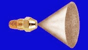
First, a source of energy is needed to break up the oil into small droplets. Therefore pressure is supplied to the nozzle, usually from a motor-driven pump at 100-150 psi. But pressure energy alone doesn’t do the job. It must first be converted to velocity energy and this is accomplished by directing the pressurized fuel through a set of slots which are cut in the distributor at an angle, or tangentially, to create a high velocity rotation within the swirl chamber. At this point, about half of the pressure energy is converted to velocity energy. As the oil swirls, centrifugal force is exerted against the sides of the chamber, driving the oil against the orifice walls, leaving a void or core of air in the centre. The oil then moves forward out of the orifice in the form of a hollow tube. The “tube” becomes a cone shaped film of oil as it emerges from the orifice, ultimately stretching to a point where it ruptures and throws off droplets of liquid.
Nozzle Selection.
T match nozzles to a burner takes experience trial and error and a good understanding, but if you are simply replacing a burner nozzle you can read the small number on the side of a nozzle and re-order the correct one. There number normall look something like 0.60 40 EH. The size 0.60, the angle 40 degrees and the pattern EH.
To insure consistent quality, every burner quality branded nozzle like Danfoss or Delevan is tested for flow rate and spray angle on modern, high instrumented test stands. Spray quality is observed during testing for uniformity, balance and flutter.
Nozzle Types or Spray pattern.
Hollow Cone Nozzle Types.

Hollow cone nozzles can be used in burners with a hollow air pattern and also for use in small burners (those firing 1.00 GPH and under), regardless of air pattern. Hollow cone nozzles generally have more stable spray angles and patterns under adverse conditions than solid cone nozzles of the same flow rate. This is an important advantage in fractional gallonage nozzles where high viscosity fuel may cause a reduction in spray angle and an increase in droplet size. Hollow nozzles produce a spray which delivers fine droplets outside the periphery of the main spray cone. These fine droplets greatly enhance ignition and create a stable flame for use with flame retention burners.
Solid Cone Nozzle Types
Solid nozzles produce a spray which distributes droplets fairly uniformly throughout the complete pattern. This spray pattern becomes progressively more hollow at high flow rates, particularly above 8.00 GPH. These nozzles may be used in larger burners (those firing above 2.00 or 3.00 GPH) to provide smoother ignition. They can also be used where the air pattern of the burner is heavy in the centre or where long fires are required.
Semi solid Nozzle Types

Semi Solid nozzles produce a spray which is neither truly hollow nor solid. These nozzles frequently can be used in place of either solid or hollow cone nozzles between .40 GPH and 8.00 GPH, regardless of the burner’s air pattern. The lower flow rates tend to be more hollow. Higher flow rates tend to be more solid.
Here is a table showing the codes for solid, semi solid and hollow nozzle codes for Danfoss, Delavan, Hago and Fluidics.

Flow Rate
Atomizing nozzles are available in a wide range of flow rates, all but eliminating the need for specially calibrated nozzles. Between 1.00 GPH and 2.00 GPH, for example, seven different flow rates are available. Generally, with hot water and warm air heat, the smallest firing rate that will adequately heat the house on the coldest day is the proper size to use and the most economical. Short on-cycles result in low efficiency. Another guideline is to select the flow rate that provides a reasonable stack temperature regardless of the connected load. (According to the New England Fuel Institute, aim for a stack temperature of 400°F or lower on matched packaged units or 500°F or lower on conversion burners.) If the boiler or furnace is undersized for the load, it may be necessary to fire for the load and ignore the efficiency
Spray Angles
Spray angles are available from 30° through 90° in most nozzle sizes to meet the requirements of a wide variety of burner air patterns and combustion chambers. Usually it is desirable to fit the spray angle to the air pattern of the burner. In today’s flame retention burner, it is possible to fire more than one spray angle with good results. Generally, round or square combustion chambers should be fired with 70° to 90° nozzles. Long, narrow chambers usually require 30° to 60° spray angles.
Effects if Pressure on Burner Nozzle Performance.
Normally, 100 psi is considered satisfactory for the fixed pressure supplied to the nozzle, and all manufacturers calibrate their nozzles at that pressure.
It is interesting to observe the sprays of a nozzle at various pressures. At the low pressure, the cone-shaped film is long and the droplets breaking off from it are large and irregular. Then, as the pressure increases, the spray angle becomes better defined. Once a stable pattern is formed, any increase in pressure does not affect the basic spray angle, measured directly in front of the orifice.
At higher pressure, however, you will note that beyond the area of the basic spray angle, the movement of droplets does make a slight change in direction inward. That’s because at this point the air pressure outside the spray cone is higher than that on the inside, which deforms the spray inward.
Pressure has another predictable effect on nozzle performance. As you would expect, an increase in pressure causes a corresponding increase in the flow rate of a nozzle, assuming all other factors remain equal. This relationship between pressure and flow rate is best shown in the table on page 13.
Increasing pressure also reduces droplet size in the spray. For example, an increase from 100 to 300 psi reduces the average droplet diameter about 28%. One last word on the subject: if pressure is too low, you may be under-firing the burner. Efficiencies may also drop sharply because droplet size is larger and the spray pattern changed. If pressure isn’t carefully checked, the marking on the nozzle becomes meaningless. Pressures of more than 100 psi are sometime desirable, but rarely do burners operate at anything less.
Nozzle Adjustments
Annual replacement of the nozzle is recommended. The nozzle size should match the design load. DO NOT OVER SIZE. (For determination of over sizing refer to publications listed on page 8.) Short cycles and low percent “on” time result in higher overall pollutant emissions and lower thermal efficiency.
An in-line oil filter will reduce problems due to nozzle clogging. It should be located as close as possible to the oil burner. Care should be taken to prevent air leakage into the oil suction line. Use continuous runs of copper tubing and use minimum number of joints and fittings. Always use flare fittings. Select the nozzle and spray pattern, whenever possible, using burner manufacturer’s instructions. On burner-boiler or burner-furnace matched assemblies, use the appliance manufacturer’s instructions. Bleed air from the pump and nozzle piping to avoid trapped air.
Nozzle Care and Service Tips
An oil burner nozzle is an intricate piece of hardware, designed to do an accurate job of atomizing and metering fuel oil in the spray pattern best suited to a given burner. You can help assure top performance of this vital component by following the important guidelines in this section
Until installation, keep nozzles in their original containers and preferably in a suitable box or rack. They should not be permitted to roll around in a drawer or toolbox, or carried loose in pockets. On service calls, they should be kept in a clean nozzle box.
Handle the nozzle carefully after removing from its individual container. Pick it up by the hex flats and by all means avoid touching the filter or strainer with greasy hands.
This can force foreign material into the nozzle where it can finally work its way into the slots. The possibility for problems is even greater with nozzles of lower flow rates since they have smaller slots…easier to clog
Nozzles should always be handled with clean tools… again to reduce the possibility of contamination. To properly service a nozzle and check its performance, it’s recommended that you use a pressure gauge, vacuum gauge, nozzle changer and flame inspection mirror.
Be sure the strainer or filter is in place on the nozzle before installation. Do not disassemble the nozzle before installing it because great care has been taken to make sure the nozzle is absolutely clean on delivery.
Frequently asked questions
I have a job on which it is difficult to clean up the fire. What should I do?
- Check the fire to see whether it is off centre (see discussion of off centre fires next column).
- Check the fan blades and if they are covered with lint and dirt, clean them.
- If this is a conventional oil burner, check for a burned-off end cone.
- Check the oil pressure to be sure that it is at least 100 psi.
- Check for a plugged line filter or pump strainer..
- If the smoke is at the outside edges of the fire, try a narrow angle nozzle.
- If the smoke occurs at the end of the fire, it might be well to try a wider spray angle.
- The burner may have insufficient air capacity for this firing rate.
- The burner may have too high air capacity for this firing rate. This would mean that the burner head couldn't handle a low firing rate.
- It might just be a very inefficient burner, which cannot be made to burn clean.
- The nozzle may be partially plugged, resulting in poor atomization.
- The oil may have a high viscosity or it might be cold, resulting in a collapsing spray.
- Get sufficient air into the boiler room. If necessary, put in an air intake pipe with a screen and storm cover.
If the burner sometimes fails to ignite smoothly and starts with a puff, what can be done to improve it?
- Check the electrode points for proper spacing. The points should be 1/8” to 3/16” apart, 9/16” above the centreline of the nozzle and then spaced correctly forward from the face of the nozzle for each different spray angle.
- Clean carbon and dirt from the points and from the insulators.
- The transformer may be weak and not delivering full voltage or current. If you don’t have another transformer immediately available, file the electrodes to a sharp point. This will give a better spark.
- Check for cracked insulators. Sometimes an insulator may be cracked under the electrode bracket and it is difficult to find. This could cause a high voltage leak, thus reducing the voltage at the points.
- A partially plugged nozzle causing off-centre spray can cause delayed ignition.
- Above about 2.50 gph a hollow cone spray sometimes may cause delayed ignition. Changing to a solid cone sometimes helps that situation.
- The air setting on the burner may be wide open, thus tending to blow the fire out before it is established. Adjust the air correctly.
Information taken from Delavan re-worked by Spares Giant
Subscribe to:
Posts (Atom)